Trentham Gardens Footbridge
Trentham Gardens Footbridge
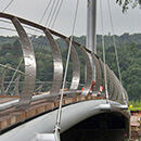
Trentham Gardens Footbridge Balustrade with Structural Support Cables

In July 2004 S3i Stainless Steel Solutions provided the 6mm cable balustrading and 16mm support cables for a new footbridge in the re-opened Trentham Gardens, Staffordshire.

Cables were swaged using a portable swaging machine which offers flexibility on-site depending on requirement. 16mm 7x19 stainless cables are used to support the bridge structure. The stainless steel wire rope used in the balustrade are 6mm 1x19.

The balustrade infill consists of a series of 30 metre single span runs of 6mm 1x19 stainless steel cable with swage studs at each end, and are secured using a nut and dome nut. These were installed with our unique pre-tensioning method and present a tamper resistant, stylish and minimalist finish.


Information about Trentham Gardens
Tag: Stainless Steel Wire, Balustrade, Tensioned, Cable, Installation, Footbridge, Trentham Gardens